This article is the following of Article #3, where a closed compartment installed in a regular Airline Cabin configuration was analyzed. This post will analyze the same small volume enclosed in a VIP configuration.
The VIP Configuration
The Ceiling and the Cargo remain the same as the Airline Configuration.
The cabin is now divided into multiple compartments. The Cabinet to be analysed as the closed-compartment (Vol#2) is installed in the Bedroom (Vol#1) — a 653ft³ volume —.
Results for VIP configuration
[SPOILER ALERT!] For those who are in a hurry, here are the results obtained with ESonix V3 for the VIP configuration.
The Table below summarizes the results obtained by ESonix software after a run considering all parameters and data described here under.
As shown in this Table and previously explained, combinations between several Cabinet Volumes and Cabinet Vent Valves were considered in the analysis. The pressure sustained for each combination is here presented in psi.
The table is formatted as in Boeing D655441 document, i.e. closed-compartment volume as horizontal entry and closed-compartment venting area as vertical entry. Differential pressures are rounded up to 2 digits.
For example, A 75ft³ closed-compartment with a 4in² gap would experience a 3.16 psi relative pressure (the same vent/volume ratio for PAX configuration was leading to 2.92 psi).
As expected, the 0in² gap leads to maximum differential pressure whatever the Cabinet volume.
Also, the greater the volume and the smaller the gap, the higher the differential pressure.
For small volumes and big gaps (lower-left corner of the table), differential pressures are low enough to be rounded to 0.
NOTE: As the Numeric Corporate Jet has been designed for training purpose only, the results of this Table doesn’t correspond to any existing commercial aircraft. In a real case scenario, the generation of this Table is made possible with ESonix using TWEAKS parameters and BATCH mode analysis. Additional information about TWEAKS parameters and BATCH mode is available in the ESonix Manuals (see Manuals). Moreover, ESonix Tutorials provides a good opportunity to practice the use of those features (see Tutorials).
The Vent/Volume ratio curve
A convenient way to display this 2D array is to show the differential pressure as a function of the vent/volume ratio.
But showing the vent/volume axis with a logarithmic scale is even more convenient:
Configuration Details
Download the ESonix numeric Corporate Jet in its VIP configuration.
The following sections show how the volumes, their connections and the load case referring to this configuration are defined for the Esonix software.
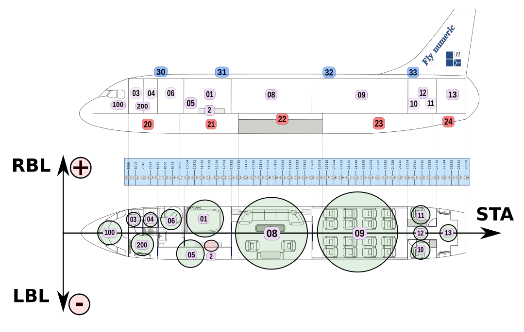
Volumes
The table below reproduces the Esonix sheet Volumes.
      id    label           deck     sta      rbl       volume
                                     [in]     [in]       [in³]

       1    Bedroom          0      11500      80      1128944.0
       2    Cabinet          0       7100     100     *variable*
       3    Lavatory         0       6200     100       164764.8
       4    VIP Lavatory     0       7700     100       170867.2
       5    Corridor         0      10500    -160       524806.4
       6    Bathroom         0       9500      80       622444.8
       8    Private Lounge   0      15500       0      2483676.8
       9    Business Class   0      22000       0      2935254.4
      10    LHS Crew Area    0      26300    -200       329529.6
      11    RHS Crew Area    0      26300     200       329529.6
      12    Hallway          0      26300       0       231891.2
      13    Rear Galey       0      29000       0       768902.4
      20    Cargo E. Bay    -1       7000       0      1220480.0
      21    FWD Cargo Bay   -1      11500       0       915360.0
      22    Over Wing       -1      17000       0       274608.0
      23    AFT Cargo Bay   -1      23000       0      1708672.0
      24    Bulk Bay        -1      28500       0       225788.8
      30    FWD Ceiling      2       7500       0        48819.2
      31    Mid Ceiling 1    2      12500       0       140355.2
      32    Mid Ceiling 2    2      21000       0       128150.4
      33    AFT Ceiling      2      26500       0        97638.4
     100    Cockpit          0       4000       0       488192.0
     200    Entrance         0       7000    -100       518704.0
Cabinet Volume and Connection
Although defined in the Esonix sheets Volume and Connections, the parameters (volume and vent area) of the Cabinet to be analysed as the closed-compartment (Vol#2), are modified by Esonix feature called Tweaks. Through this feature (Tweaks) the Cabinet Volume varied from 5 in³ to 150 in³ and the Cabinet Vent Area varied from 0 in² to 70 in².
NOTE: The user can check the Tutorial #6 of Esonix manual for additional information about the Tweaks feature of Esonix software.
Load Case
The VIP Configuration analysis assumes an opening hole on the Bedroom (Vol#01), where the Cabinet (Vol#02) is installed. The initial pressure differential between the cabin and the ambient is 8.6psi.
Connections
Four types of connection between the aircraft volumes are considered in the VIP Configuration. They are:
- Active Vents
The following figure illustrates the active vents (B01, B02, B03, B04, B05, B08, B09, B10, B11 and B12) considered in the VIP Configuration.
The following table shows how these active vents are considered by Esonix on its sheet Connections.
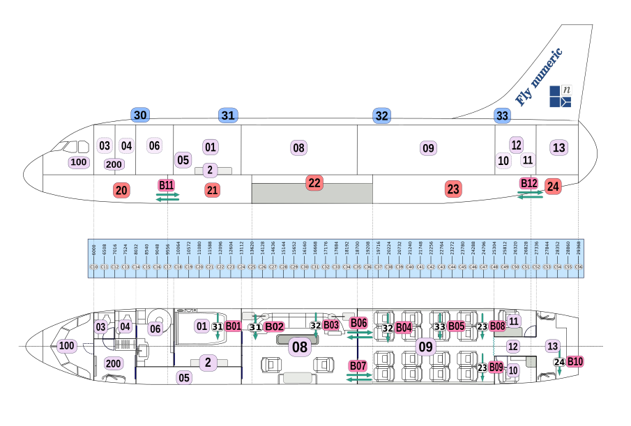
    id   vol_i  vol_j  comments                    vent_area    open._pres    cp     vent_area   open._pres    cp
                                                    i_to_j       i_to_j     i_to_j     j_to_i     j_to_i     j_to_i
                                                    [in²]         [psi]       [-]       [in²]      [psi]       [-]

    51    1     31     Ceiling Blowout panel B01      0             0          0      387.50      0.2175       0.6
    52    8     31     Ceiling Blowout panel B02      0             0          0     1162.50      0.2175       0.6
    53    8     32     Ceiling Blowout panel B03      0             0          0     1162.50      0.2175       0.6
    54    9     32     Ceiling Blowout panel B04      0             0          0     1271.00      0.2175       0.6
    55    9     33     Ceiling Blowout panel B05      0             0          0     1271.00      0.2175       0.6
    56    8      9     Wall Blowout panel B06      387.50         0.435       0.6       0            0          0
    57    8      9     Wall Blowout panel B07      387.50         0.435       0.6       0            0          0
    58   11     23     Floor Blowout panel B08     310.00         0.435       0.6       0            0          0
    59   10     23     Floor Blowout panel B09     310.00         0.435       0.6       0            0          0
    60   13     24     Floor Blowout panel B10     310.00         0.435       0.6       0            0          0
    61   20     21     Cargo Blowout panel B11     434.00         0.508       0.6     697.50      0.4350        0
    62   23     24     Cargo Blowout panel B12     465.00         0.435       0.6     620.00      0.5075        0
- Passive Vents
The following figure illustrates the passive vents (V01, V02, V03, V04, V05, V06, V07, V08, V11, V12, V13, V14, V15, V16, V17, V18, V19, V20, V21), considered in the VIP Configuration.
The passive vent between Cabinet and Bedroom is also defined here, although this connections is variable as explained below.
The following table shows how these passive vents are considered by Esonix on its sheet Connections.
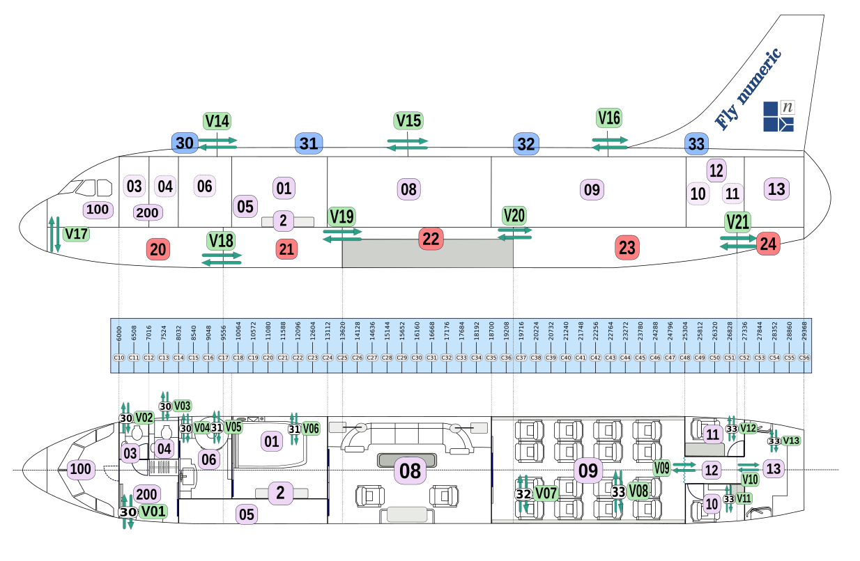
    id  vol_i  vol_j  comments              vent_area       cp
                                              i_to_j      i_to_j
                                               [in²]        [-]

     1    1       2   Cabinet to Bedroom    *variable*     0.60
    11   30     200   Passive Vent V01         15.5        0.45
    12    3      30   Passive Vent V02         15.5        0.45
    13    4      30   Passive Vent V03         15.5        0.45
    14    6      30   Passive Vent V04         77.5        0.45
    15    6      31   Passive Vent V05         15.5        0.45
    16    1      31   Passive Vent V06         31.0        0.45
    17    9      32   Passive Vent V07         46.5        0.45
    18    9      33   Passive Vent V08         46.5        0.45
    19    9      12   Passive Vent V09       2604.0        0.45
    20   12      13   Passive Vent V10       2604.0        0.45
    21   10      33   Passive Vent V11         46.5        0.45
    22   11      33   Passive Vent V12         46.5        0.45
    23   13      33   Passive Vent V13         77.5        0.45
    24   30      31   Passive Vent V14         46.5        0.45
    25   31      32   Passive Vent V15        108.5        0.45
    26   32      33   Passive Vent V16         31.0        0.45
    27   20     100   Passive Vent V17        542.5        0.45
    28   20      21   Passive Vent V18        310.0        0.45
    29   21      22   Passive Vent V19        310.0        0.45
    30   22      23   Passive Vent V20        310.0        0.45
    31   23      24   Passive Vent V21        232.5        0.45
- Door Vents
The following figure illustrates the doors considered in VIP Configuration.
The following table shows how the doors and its vents are considered by Esonix on its sheet Connections.
The Cockpit Door (D01) is equipped with two blowout panels, see ids #80 and #81 in the table.
The other Doors (D02, D03, D04, D05, D06, D07, D08, D09, D10) are Swivel os Sliding doors as identified in the table.
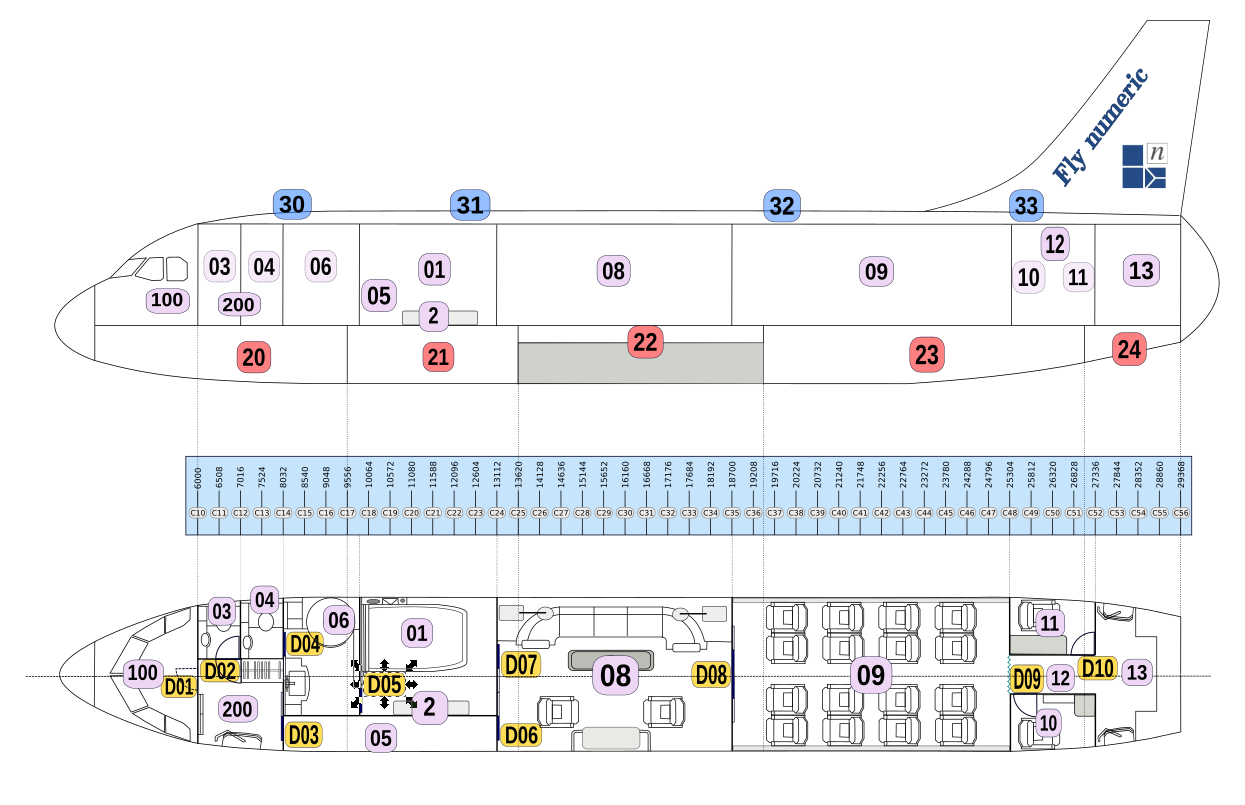
    id  vol_i  vol_j  comments                       door  vent_area   open._pres.   cp     vent_area   open._pres.  cp
                                                            i_to_j      i_to_j     i_to_j    j_to_i       j_to_i    j_to_i
                                                     [in²]   [in²]       [psi]       [-]      [in²]        [psi]     [-]

     2     3    200   Lavatory swivel door D02       2480   2480.0        0.29       0.6      2480.0       0.29      0.6
     3     5    200   Corridor sliding door D03      3100   1162.5        0.29       0.6      1162.5       0.29      0.6
     4     4      6   VIP Lavatory sliding door D04  2945   1162.5        0.29       0.6      1162.5       0.29      0.6
     5     1      6   Bathroom sliding door D05      2945   1162.5        0.29       0.6      1162.5       0.29      0.6
     6     5      8   Corridor sliding door D06      3100   1162.5        0.29       0.6      1162.5       0.29      0.6
     7     1      8   Bedroom sliding door D07       2945   1162.5        0.29       0.6      1162.5       0.29      0.6
     8     8      9   Double sliding doors D08       6665                  0         0.6                     0       0.6
     9    10     12   LHS Crew rest swivel door D09  2790      0           0         0.6        2790       0.29      0.6
    10    11     12   RHS Crew rest swivel door D10  2790      0           0         0.6        2790       0.29      0.6
    80   100    200   Cockpit door  Blow out 01       0        0           0          0        325.5       0.58      0.6
    81   100    200   Cockpit door  Blow out 02       0        0           0          0        480.5       0.58      0.6
- Side Vents
The following table shows the Side Vents considered in the Esonix table Connections. Side Vents are passive vents between the Main Deck and the Cargo Deck.
    id  vol_i  Vol_j  comments  vent_area      cp
                                 i_to_j      i_to_j
                                  [in²]        [-]

    32     4     20   RHS Vent     37.2       0.45
    33     6     20   RHS Vent     55.8       0.45
    34     6     21   RHS Vent     10.1       0.45
    35     1     21   RHS Vent     70.5       0.45
    36     8     21   RHS Vent     23.3       0.45
    37     8     22   RHS Vent    182.1       0.45
    38     9     22   RHS Vent     40.7       0.45
    39     9     23   RHS Vent    187.2       0.45
    40    11     23   RHS Vent     49.6       0.45
    41    11     24   RHS Vent      6.2       0.45
    42    20    200   LHS Vent     77.5       0.45
    43     5     20   LHS Vent     55.8       0.45
    44     5     21   LHS Vent    119.4       0.45
    45     8     21   LHS Vent     15.5       0.45
    46     8     22   LHS Vent    182.1       0.45
    47     9     22   LHS Vent     40.7       0.45
    48     9     23   LHS Vent    187.2       0.45
    49    10     23   LHS Vent     49.6       0.45
    50    10     24   LHS Vent      6.2       0.45
NEXT STEP…
In the next Article will compare the Small Volume Decompression results of both configurations of Numeric Corporate Jet: Airline/PAX configuration and VIP configuration.
See here the list of Articles referring to the study of Small Volume Decompression:
-
Article #1: Small Volumes Decompression #1 - Understanding the Problem
-
Article #2: Small Volumes Decompression #2 - Airline/Pax, VIP configurations and Aircraft Parameters
-
Article #3: Small Volumes Decompression #3 - Analysis of closed compartment in the Cabin Airline/PAX Configuration
-
Article #4: Small Volumes Decompression #4 - Analysis of closed compartment in the Cabin VIP Configuration
-
Article #5: Small Volumes Decompression #5 - Airline X VIP Results Comparison
-
Article #6: Small Volumes Decompression #6 - Airline X VIP Results Comparison (Further Step)
-
Article #7: Small Volumes Decompression #7 - Decompression Analysis considering the Cabinet Stiffness
-
Article #8: Small Volumes Decompression #8 - Study summary and conclusions