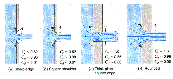
What are discharge coefficients?
Aircraft decompression analysis performed using thermodynamics relies on a model made of a network of volumes connected by vents.
In this acceptation, a vent provides a way for the air to move from one volume to another one. Its main characteristic is thus its area; the bigger it is, the easier it will be for the air to move on.
However, the gross area need to be reduced by a discharge coefficient. Those coefficients reduce the Actual area to an Effective area.
Discharge coefficients depend on:
The dependence to pressure ratio implies that Discharge coefficients will change with respect to the time and should thus be dynamically computed. It is however admitted to fix them once for all.

Cabin to Ambient Discharge Coefficient
This Discharge Coefficient is treated separately due to highest flow speed going through the explosion hole.
The flow is very often supersonic at the beginning of the process and CD is thus reduced.
From FAA AC25-20, §8f:
“In calculating the cabin altitude decompression profile, unless a different value can be established by a rational analysis acceptable to the FAA, an orifice discharge coefficient of \(Cd = 0.75\) for loss of a window and \(Cd = 0.5\) for a hole resulting from fuselage damage should be assumed”
We can assume that the high Discharge Coefficient used for the loss of window is due to the clean way it opens for the air, by opposition to the hole resulting of fuselage damage.
Cabin internal Discharge Coefficients
Internal discharge coefficients are not determined by regulations, but should be reasonably chosen based on geometries.
A good starting point is:
- \(Cd=0.8\): Wide ways (like artificial division between big volumes).
- \(Cd=0.6\): Large, clean ways like doors.
- \(Cd=0.4\) to \(0.45\): exotic width/height ratios, or grids, dado panels, etc..
For more exotic geometries or situations, a CFD analysis can be performed to determine the Discharge Coefficient.